Problem Statement
In my first lab, of which I was a part for most of my undergrad, part of my role involved fluorescence microscopy on an Olympus MVX10. To hold standard microscope slides for imaging, the lab used a Sutter micromanipulator typically used for stereotaxic injections. This micromanipulator was uncalibrated, and therfore jumpy. More importantly, the horizontal (and vertical) range of the stage was less than the 50mm functional width of a slide. This meant manual adjusting under a curtain designed to block light, and a subsequent readjusting of the microscope to focus after poking at the slide. In short, it cost imaging time in a shared lab, involved constant adjustment, and took up an otherwise useful micromanipulator.
Below I detail a large scale overview of the progression of this project. Each "version" required multiple small design changes and re-prints; they are simply grouped for simplicity.
1. Sliding Mechanism
A) Version 1
The first objective was designing the sliding mechanism. Early iterations included fully 3D-printed trapezoidal tracks like those on old cryotomes, vises, or precisely milled metal parts. This almost immediately ran into size constraints, inconsistencies with the top layer, and fit complications due to warping on the heat bed.
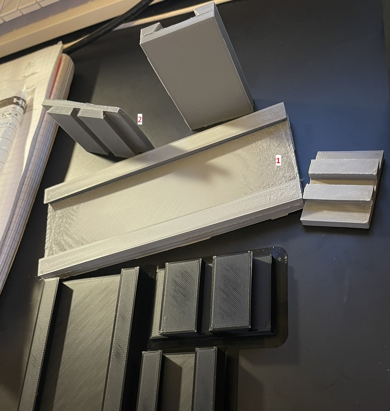
B) Version 2
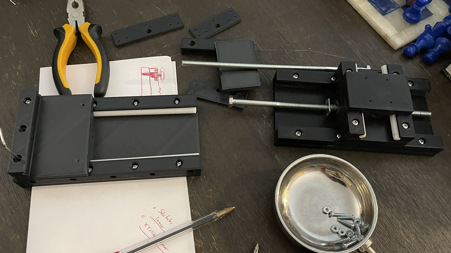
In the previous photo, you can see the next set of designs using the black plastic that solved both these issues, but still had gaps and would bind up sometimes. In the spirit of accessibility, the use of milling, or expensive metal parts was not an option. I, however, still wanted tight tolerances, free movement, and adjustability over time. Therefore, I switched from the trapezoidal to a rectangular profile, and made the side rails separate parts from a flat base (see below). To solve the issue of vertical play, I then added a circular rod of low-friction plastic which I believe was around $10. This acted as both a point of contact, and a source of adjustable compression. In the photo below, the separation of the slide rails and the bottom face are visible on the left side. They are attached with screws, allowing for some adjustability. The version on the right, expands on this with oval screw holes (more accurately. geometric stadiums) that can allow sliding, and tightening once in place. I am spoiling this a bit with the picture, but you can also see that a Y axis was added and end caps of the slides were created to hold a driving screw/bolt. Special nuts were affixed to the traveling component, which I refer to as a "sled" to allow it to move linearl from the rotation of the bolt. Do note that the "sled " for the x-axis also serves as the base for the y-axis.
2. Movement
The previous picture doesn't address how the central driving bolt remains stationary to allow the sled to move relative to the base. This was done by simply adhering nuts onto the bolt as you can see below. This way it acts in the same way a linear actuator turns rotational motion into linear motion. Why use a bolt? Its cheap, accurate enough, and the availability of different nuts like those I use in the picture below (Nylon nuts on the driving bolt, "T" nut in the sleds) is ideal for copying this project. You can also see that the Y axis is simply a shorter copy of the x. While the nuts on the driving bolt are slightly different (I ran out when this picture was taken), They function the same way to keep the rod from moving in the direction of its long axis. Initially they were mounted in place up against the end face plates of the slides, but to spread the distribution of force and ideally wear, I also printed some spacers. Also of note is the adapter coupling the motor shaft to the bolt, which is essentially just a socket.
3. Electronics
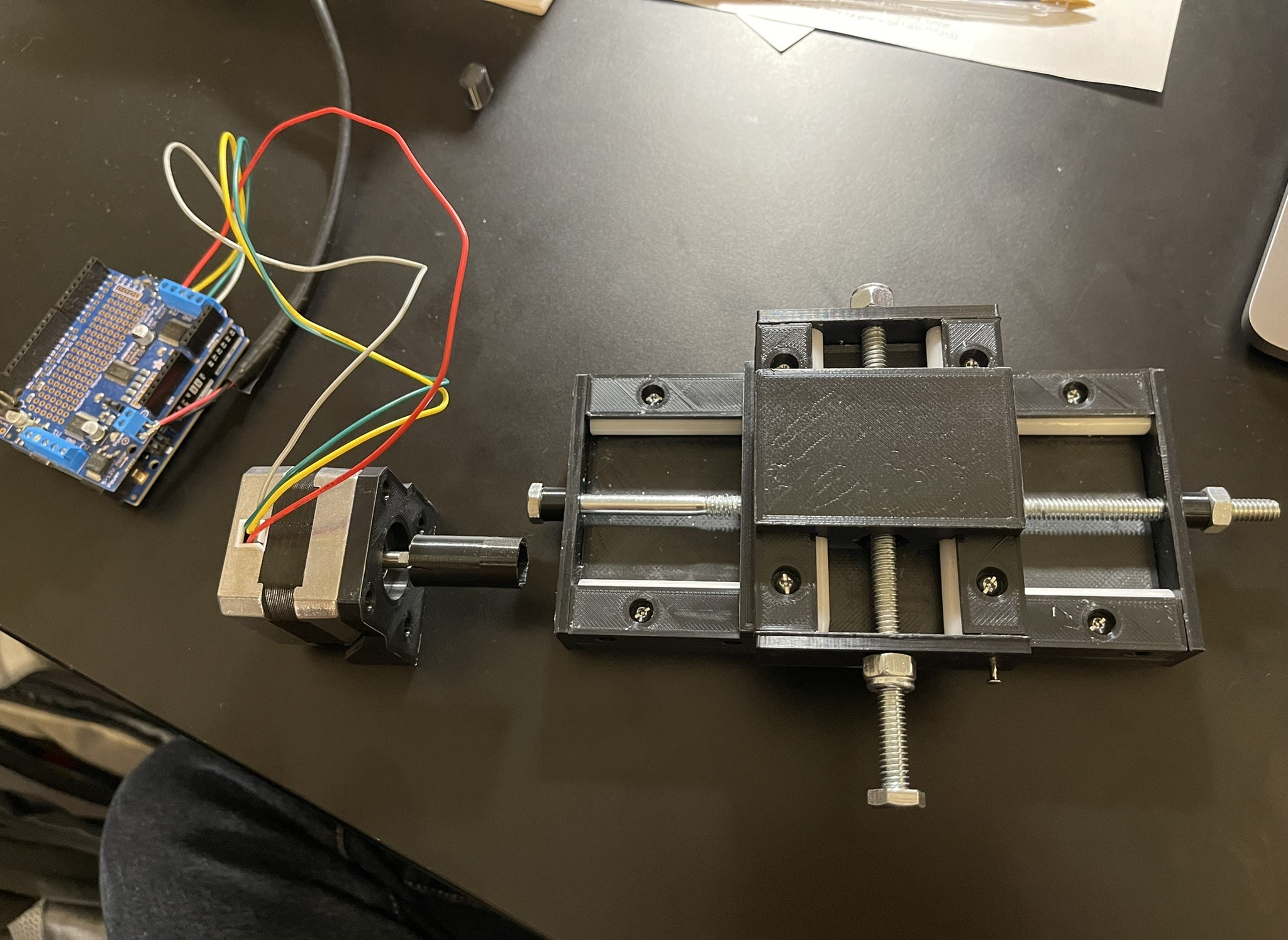
With the X and Y slide axes largely completed, figuring out the motors and wiring seemed a reasonable next step. I had already planned to use a standard stepper motor for precise control of the x axis, but for the Y, I would need a smaller motor and room for whatever the Z axis requires. I figured I might eventually come up with a belt-driven solution that reduces weight on a moving part. To be honest, I still haven't figured this part out. I ended up using an expensive solution with belts on a version made for the lab (still both cheaper and fully capable), but I don't feel that it fits the accesibility theme of this project. For now, I simply used the one motor I hooked up to test both axes, and moved on to the controller, which I find more topical to this section. The controller has two main inputs, a joystick (basically two potentiometers) and a rotary encoder that uses the turning of a magnet for unlimited spinnning as opposed to potentiometers with hard stops. Connecting the joystick to the arduino as an input is really quite simple. As you can see in the video, I just run a 5v output from the power on the protoboard through the joystick's two axes, and then back into an analog input pin, using the joystick as a variable resistor. The microcontroller receives some fraction of the original 5 volts, telling it the position of the joystick on essentially a coordinate plane. I think protoboards are perfect for a project like this because they can be permanent solutions, without custom designing and ordering of PCB's. They are cheaper, there is no wait time, and it's customizable if you make a mistake! Anyways, the rotary encoder will serve as the controller of the Z-axis, and there isn't necessarily any reason it has to be free-spinning, other than the fact that I want the controls to reflect movement, rather than absolute position. The benefit of this is that if the joystick or encoder are slighly off center on startup or anytime after, we don't want to get background movement (see a phenomenon called "stick drift"). If I end up adding some distance readout, say for stereotaxic injections, it will be a separate system. Also readily available on amazon are simply rotary encoder chips you can buy that come with a magnet. As the magnetic field rotates at a set distance from the encoder, a digital signal can be sent to the arduino. This is notably different from the analog symbol sent by the joystick. Finally to transmit this signal, I am using short range 2.4 GHz wireless transmitters that can be paired on specific wavelengths. Supposedly the range is quite far, but I only really need it across a table length for this application. The whole controller itself is powered by a 9v and a board that splits power to 5v and 3.3v for the analog and digital outputs respectivaly. Of importance is that the transmitter board can only handle 3.3v. 5v will create artifacts.
I will be updating this page with whatever I figure out for the Y and Z axes, but due to move and a new full-time job, it may be a while before I can post a write-up for it.
Updates
- 2025-05-26: This is a placeholder for future updates.